Why Your Scanner Might Be Lying to You about Fuel Trim
In the hierarchy of automotive diagnostics, the oxygen sensor (O2 sensor) stands as the primary feedback mechanism for the Electronic Control Unit (ECU). While most DIYers reach for a cheap OBD-II code reader when a P0420 or P0171 code appears, a seasoned mechanic knows that serial data can be deceptive. Scanners often display a calculated PID (Parameter Identification) value that can be buffered or delayed by the ECU’s internal processing logic. To truly understand if a sensor is sluggish—a condition often missed during a standard tune up—you need to intercept the raw analog signal. Using a $15 multimeter allows you to bypass the digital filter and see the voltage fluctuations in real-time, providing a level of diagnostic precision usually reserved for high-end oscilloscopes.
Can a Budget Multimeter Actually Replace High-End Diagnostic Scopes?
The short answer is: for narrow-band sensors, yes, provided you understand the limitations of your tool’s sampling rate. A standard zirconium dioxide sensor operates on the Nernst principle, generating its own voltage based on the oxygen differential between the exhaust stream and the ambient atmosphere. According to technical insights from Delphi Technologies, a healthy sensor should oscillate between approximately 0.1V and 0.9V multiple times per second at 2,000 RPM. While a budget multimeter won’t capture the fine ‘hash’ of a signal like a Lab Scope, it is more than capable of confirming if the sensor is ‘stuck’ lean or rich, or if it has become ‘lazy’ due to silica contamination or carbon soot. If you’re struggling to find the right professional to assist with these deeper auto repair issues, learning how to choose a skilled mechanic you can trust is your next logical step.
Mastering the Back-Probe Without Damaging the Harness
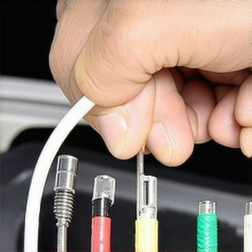
The biggest risk in O2 sensor testing isn’t the voltage—it is the physical integrity of the wiring. You must never pierce the insulation of the wires, as this introduces a path for moisture and eventual corrosion, leading to ‘ghost’ resistance that will haunt your fuel trims for months. Instead, use a thin T-pin to back-probe the connector. This involves sliding the pin along the wire into the back of the weather-pack seal until it contacts the metal terminal. By connecting your multimeter to this pin and a known good chassis ground, you can observe the sensor’s reaction to engine load changes. This is a critical step in a comprehensive auto repair strategy, especially when a vehicle fails an emissions test despite having new spark plugs.
Often, a ‘bad sensor’ is actually the victim of an upstream vacuum leak. Before condemning the part, try the $5 soapy water trick for finding intake leaks. If the sensor reacts instantly to a shot of propane or carb cleaner into the intake, the sensor is likely functional, and your problem lies elsewhere in the combustion loop.
Is Your Sensor Reacting Fast Enough for the Modern ECU?
A ‘lazy’ sensor is one that still switches but does so too slowly to maintain the tight stoichiometric control required by modern catalytic converters. During a brake service or routine oil change, most people ignore the O2 sensor until the light comes on, but a slow sensor can drop your fuel economy by 10-15% without ever triggering a DTC (Diagnostic Trouble Code). If your multimeter shows fewer than 8-10 transitions over a 10-second window at high idle, the sensor is functionally end-of-life. If you’ve identified a sluggish sensor, don’t stop at the exhaust; ensure your ignition system is providing the spark necessary for a clean burn by following our ultimate tune-up checklist for every car owner. Identifying these nuances is what separates a parts-changer from a true diagnostic expert.
Why a Flat-Lined Post-Cat Sensor is Your Best Friend
In the world of post-catalytic converter monitoring, the rules of the diagnostic game change significantly. While the upstream sensor must switch rapidly to prove the system is in closed-loop, a healthy downstream sensor—often labeled Sensor 2—should remain relatively stable around 0.45V to 0.6V. If your multimeter or scanner shows the downstream sensor mirroring the rapid oscillations of the upstream unit, it is a definitive signal that the catalytic converter has lost its oxygen storage capacity. This degradation is rarely a standalone failure; it is usually the result of long-term exposure to oil blow-by or excessive unburned fuel. To prevent this, experts often look toward small but vital components, such as the $14 PCV valve fix that stops engine oil consumption, which can save a $1,200 converter from premature death.
Force the ECU to Reveal Its Hidden Fuel Trim Secrets
Diagnostic mastery requires correlating O2 sensor voltage with fuel trim data to find the root cause of a rough idle. Short-term fuel trim (STFT) represents the immediate reaction, while long-term fuel trim (LTFT) shows the historical trend. If your sensor reports a lean condition (low voltage) and your total fuel trim is positive 20%, the ECU is desperately dumping fuel to compensate for air it didn’t account for. Before you blame the sensor, check for unmetered air entering through the intake. Sometimes, the solution is as simple as the $15 sensor that fixes your rough idle in minutes, often referring to a contaminated Mass Air Flow (MAF) sensor that is providing skewed data to the primary feedback loop.
What Happens When Your Wideband Sensor Reports Current Instead of Voltage?
Modern performance vehicles and many late-model commuters have moved away from traditional narrowband sensors in favor of Wideband Air/Fuel (A/F) Ratio sensors. Unlike the older Nernst cells that toggle like a light switch, wideband sensors use a ‘pump cell’ to maintain a constant internal voltage. According to engineering documentation from Bosch Mobility, these sensors communicate with the ECU via a varying current measured in milliamperes. You cannot test these with a standard voltmeter across the signal wires in the traditional sense, as the ECU’s internal circuitry is constantly adjusting the current to keep the lambda at 1.0. Attempting to ‘jump’ these wires can instantly fry the sensitive A/F controller inside the ECU, making it imperative to use a high-end scan tool for these specific components.
The Invisible Vacuum Leak That Fools Even Expert Mechanics
One of the most frustrating scenarios in auto repair is the ‘False Lean’ reading. This occurs when an exhaust leak exists upstream of the O2 sensor. When the exhaust pulse passes the leak, a venturi effect pulls ambient air into the stream. The O2 sensor detects this extra oxygen and tells the ECU the engine is running lean, even if the combustion is actually perfect. The ECU responds by adding fuel, causing the car to run rich, soot up the spark plugs, and eventually fail emissions. If you suspect your sensor is lying because of a physical breach in the pipe, you should learn how to spot a leaky exhaust manifold without removing the heat shield. This diagnostic step ensures you aren’t replacing expensive electronics when a $10 gasket is the real culprit behind why your vehicle still fails emissions after a professional exhaust repair. If you found these technical deep-dives helpful, consider sharing this guide with a fellow gearhead or leave a comment below about the weirdest ‘ghost’ code you have ever chased.
Stop Letting Ground Offsets Ruin Your Diagnostic Accuracy
Even the most precise multimeter readings are useless if you are measuring against a corrupted reference. In many 1990s and 2000s era vehicles, the ECU uses a ‘floating ground’ for the oxygen sensor to isolate it from the high-voltage noise generated by the ignition system. If you ground your multimeter to the battery negative terminal instead of the dedicated sensor ground wire, you might see a 200mV offset that doesn’t actually exist in the engine’s reality. This phantom voltage can lead a mechanic to believe the engine is running richer than it truly is, causing unnecessary parts replacement. Always cross-reference your sensor ground to the engine block; any reading over 50mV suggests a frayed wiring harness or a corroded chassis ground rather than a faulty sensor. This level of attention to detail is what defines a professional tune up on a high-mileage engine.
Why Does My O2 Sensor Voltage Drop to Zero When I Let Off the Gas?
It is a common panic point for DIY enthusiasts: you’re monitoring live data during a test drive, you lift your foot off the accelerator to coast, and the voltage suddenly flat-lines at 0.0V. This isn’t a sign of a dead sensor; it is a function of Deceleration Fuel Cut-Off (DFCO). Modern ECUs are programmed to shut down the fuel injectors entirely when the throttle is closed and the engine is being driven by the vehicle’s momentum. According to technical documentation from NGK Spark Plugs (U.S.A.), Inc., this intentional lean-out condition is a standard calibration strategy to improve fuel economy and reduce pumping losses. If your sensor voltage doesn’t drop to near-zero during coasting, you likely have a leaking fuel injector or a sticking throttle plate that is preventing the ECU from entering its most efficient state.
Beat the Heater Circuit Gremlins with a Quick Resistance Check
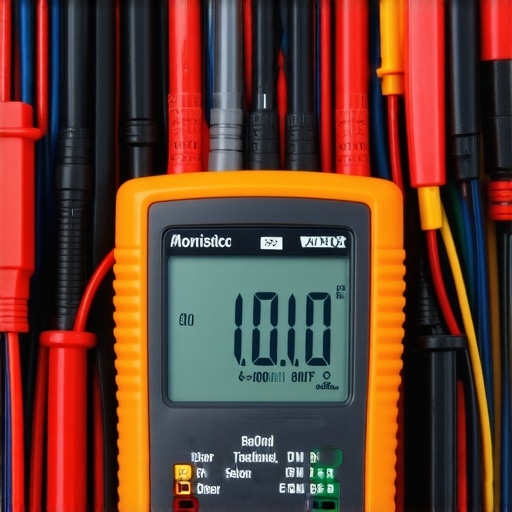
Most O2 sensor trouble codes aren’t actually triggered by the sensing element itself, but by the failure of the internal heater. To reach the ‘light-off’ temperature of roughly 600°F quickly, sensors rely on an internal heating element often controlled by the ECU through Pulse Width Modulation (PWM). If the heater fails, the sensor will never reach operational temperature at idle, leaving the vehicle stuck in ‘open-loop’ mode where it ignores real-time feedback. During a standard brake service or routine inspection, it takes less than two minutes to unplug the sensor and check the heater resistance—usually between 2 and 20 ohms depending on the manufacturer. If your meter shows infinite resistance (OL), the internal ceramic heater has cracked, and the sensor is effectively a paperweight. If you’re tired of chasing electrical phantoms, checking out our guide on how to diagnose electrical shorts without blowing fuses can save you hours of frustration.
Spotting the Chemical Poisoning That Slowly Kills Your Catalyst
Beyond electrical failures, the physical environment of the exhaust stream is incredibly hostile. A sensor might switch perfectly today but die tomorrow due to chemical poisoning. Silicone contamination, often caused by using the wrong type of RTV sealant during a previous auto repair, creates a white, powdery coating on the sensor tip that prevents oxygen ions from reaching the zirconium element. Similarly, if your engine is consuming oil, phosphorus from the oil additives can ‘glaze’ the sensor, making it sluggish and unresponsive. When you pull a sensor for inspection, the color of the tip tells a story: a dark, sooty tip indicates a rich condition, while a white or grainy tip suggests chemical interference. Before you install a replacement, it is vital to identify if the root cause is a failing internal seal or an external additive, as the same fate will surely befall your new component.
Digital Ghosts in the CAN-Bus Highway
As modern vehicles move toward more integrated architectures, the gap between what an oxygen sensor produces and what your scanner displays is widening. While your analog multimeter shows a crisp, 100ms switch, the data on your scan tool might appear jagged or ‘chopped.’ This is often due to Controller Area Network (CAN) bus prioritization, where the Electronic Control Unit (ECU) prioritizes safety-critical data like steering angle or braking pressure over the diagnostic feedback of a secondary O2 sensor. This ‘digital lag’ can lead a mechanic to believe a sensor is failing when the network itself is simply congested. To verify this, a technician must compare the raw voltage at the sensor pin to the data stream PID (Parameter Identification) to ensure no signal aliasing is occurring.

The Hidden Link Between Your Brake Booster and Lean Codes
A common diagnostic pitfall occurs during a standard brake service or inspection when a vehicle presents a mystery P0171 (lean bank 1) code that only appears at stoplights. Because the power brake booster relies on engine vacuum, a microscopic tear in its internal diaphragm can act as a massive, intermittent vacuum leak. When you depress the brake pedal, you are essentially opening an unmetered air valve that the O2 sensor immediately detects as a lean spike. A true expert won’t just throw a sensor at the problem; they will plug the vacuum line to the booster and watch the fuel trims. If the trims normalize instantly, the issue isn’t the auto repair of the fuel system, but a mechanical failure of the braking assist circuit. This illustrates why auto repair requires a holistic understanding of how separate vehicle systems interact under load.
Why do manufacturers release PCM updates to solve sensor ‘slow response’ codes?
Sometimes, the sensor isn’t at fault, but the software’s tolerance for it is. In many late-model vehicles, manufacturers issue Technical Service Bulletins (TSBs) that involve a Power Control Module (PCM) reflash rather than a parts replacement. These updates often widen the ‘switching window’ or adjust the sensitivity of the monitor for aged sensors. According to the technical standards documented by SAE International in their J1979 OBD-II communication protocols, the logic used to determine a ‘lazy’ sensor is entirely proprietary to the OEM. If you’ve replaced a sensor and the code returns, checking for a PCM update is the professional move that prevents costly ‘parts-cannon’ diagnostics. This nuanced approach is a hallmark of a high-quality tune up in the modern era.
Stop Aftermarket Exhausts from Blinding Your ECU
Upgrading to a high-flow exhaust or performance headers can inadvertently sabotage your engine’s efficiency. When you change the geometry of the exhaust manifold, you change the ‘scavenging’ effect—the pulse of vacuum that helps pull exhaust gases out of the cylinder. If the O2 sensor is relocated even a few inches away from its original factory position, it may end up in a ‘dead zone’ where exhaust gases swirl or stagnate. This leads to a false-rich or false-lean reading because the sensor is no longer seeing a representative sample of the combustion events. If your vehicle feels sluggish after an exhaust mod, the sensor might be perfectly healthy but effectively ‘blinded’ by the new airflow patterns. Before you assume you need more auto repair work, ensure the sensor bung is positioned in the high-velocity stream of the exhaust pipe. Take your diagnostic skills to the professional level by analyzing your vehicle’s long-term fuel trim trends today to see the real impact of your modifications.
Why Your Scanner Might Be Lying to You about Fuel Trim
In the hierarchy of automotive diagnostics, the oxygen sensor (O2 sensor) stands as the primary feedback mechanism for the Electronic Control Unit (ECU). While most DIYers reach for a cheap OBD-II code reader when a P0420 or P0171 code appears, a seasoned mechanic knows that serial data can be deceptive. Scanners often display a calculated PID (Parameter Identification) value that can be buffered or delayed by the ECU’s internal processing logic. To truly understand if a sensor is sluggish—a condition often missed during a standard tune up—you need to intercept the raw analog signal. Using a $15 multimeter allows you to bypass the digital filter and see the voltage fluctuations in real-time, providing a level of diagnostic precision usually reserved for high-end oscilloscopes.
Can a Budget Multimeter Actually Replace High-End Diagnostic Scopes?
The short answer is: for narrow-band sensors, yes, provided you understand the limitations of your tool’s sampling rate. A standard zirconium dioxide sensor operates on the Nernst principle, generating its own voltage based on the oxygen differential between the exhaust stream and the ambient atmosphere. According to technical insights from Delphi Technologies, a healthy sensor should oscillate between approximately 0.1V and 0.9V multiple times per second at 2,000 RPM. While a budget multimeter won’t capture the fine ‘hash’ of a signal like a Lab Scope, it is more than capable of confirming if the sensor is ‘stuck’ lean or rich, or if it has become ‘lazy’ due to silica contamination or carbon soot. If you’re struggling to find the right professional to assist with these deeper auto repair issues, learning how to choose a skilled mechanic you can trust is your next logical step.
Mastering the Back-Probe Without Damaging the Harness
The biggest risk in O2 sensor testing isn’t the voltage—it is the physical integrity of the wiring. You must never pierce the insulation of the wires, as this introduces a path for moisture and eventual corrosion, leading to ‘ghost’ resistance that will haunt your fuel trims for months. Instead, use a thin T-pin to back-probe the connector. This involves sliding the pin along the wire into the back of the weather-pack seal until it contacts the metal terminal. By connecting your multimeter to this pin and a known good chassis ground, you can observe the sensor’s reaction to engine load changes. This is a critical step in a comprehensive auto repair strategy, especially when a vehicle fails an emissions test despite having new spark plugs.
Often, a ‘bad sensor’ is actually the victim of an upstream vacuum leak. Before condemning the part, try the $5 soapy water trick for finding intake leaks. If the sensor reacts instantly to a shot of propane or carb cleaner into the intake, the sensor is likely functional, and your problem lies elsewhere in the combustion loop.
Is Your Sensor Reacting Fast Enough for the Modern ECU?
A ‘lazy’ sensor is one that still switches but does so too slowly to maintain the tight stoichiometric control required by modern catalytic converters. During a brake service or routine oil change, most people ignore the O2 sensor until the light comes on, but a slow sensor can drop your fuel economy by 10-15% without ever triggering a DTC (Diagnostic Trouble Code). If your multimeter shows fewer than 8-10 transitions over a 10-second window at high idle, the sensor is functionally end-of-life. If you’ve identified a sluggish sensor, don’t stop at the exhaust; ensure your ignition system is providing the spark necessary for a clean burn by following our ultimate tune-up checklist for every car owner. Identifying these nuances is what separates a parts-changer from a true diagnostic expert.
Why a Flat-Lined Post-Cat Sensor is Your Best Friend
In the world of post-catalytic converter monitoring, the rules of the diagnostic game change significantly. While the upstream sensor must switch rapidly to prove the system is in closed-loop, a healthy downstream sensor—often labeled Sensor 2—should remain relatively stable around 0.45V to 0.6V. If your multimeter or scanner shows the downstream sensor mirroring the rapid oscillations of the upstream unit, it is a definitive signal that the catalytic converter has lost its oxygen storage capacity. This degradation is rarely a standalone failure; it is usually the result of long-term exposure to oil blow-by or excessive unburned fuel. To prevent this, experts often look toward small but vital components, such as the $14 PCV valve fix that stops engine oil consumption, which can save a $1,200 converter from premature death.
Force the ECU to Reveal Its Hidden Fuel Trim Secrets
Diagnostic mastery requires correlating O2 sensor voltage with fuel trim data to find the root cause of a rough idle. Short-term fuel trim (STFT) represents the immediate reaction, while long-term fuel trim (LTFT) shows the historical trend. If your sensor reports a lean condition (low voltage) and your total fuel trim is positive 20%, the ECU is desperately dumping fuel to compensate for air it didn’t account for. Before you blame the sensor, check for unmetered air entering through the intake. Sometimes, the solution is as simple as the $15 sensor that fixes your rough idle in minutes, often referring to a contaminated Mass Air Flow (MAF) sensor that is providing skewed data to the primary feedback loop.
What Happens When Your Wideband Sensor Reports Current Instead of Voltage?
Modern performance vehicles and many late-model commuters have moved away from traditional narrowband sensors in favor of Wideband Air/Fuel (A/F) Ratio sensors. Unlike the older Nernst cells that toggle like a light switch, wideband sensors use a ‘pump cell’ to maintain a constant internal voltage. According to engineering documentation from Bosch Mobility, these sensors communicate with the ECU via a varying current measured in milliamperes. You cannot test these with a standard voltmeter across the signal wires in the traditional sense, as the ECU’s internal circuitry is constantly adjusting the current to keep the lambda at 1.0. Attempting to ‘jump’ these wires can instantly fry the sensitive A/F controller inside the ECU, making it imperative to use a high-end scan tool for these specific components.
The Invisible Vacuum Leak That Fools Even Expert Mechanics
One of the most frustrating scenarios in auto repair is the ‘False Lean’ reading. This occurs when an exhaust leak exists upstream of the O2 sensor. When the exhaust pulse passes the leak, a venturi effect pulls ambient air into the stream. The O2 sensor detects this extra oxygen and tells the ECU the engine is running lean, even if the combustion is actually perfect. The ECU responds by adding fuel, causing the car to run rich, soot up the spark plugs, and eventually fail emissions. If you suspect your sensor is lying because of a physical breach in the pipe, you should learn how to spot a leaky exhaust manifold without removing the heat shield. This diagnostic step ensures you aren’t replacing expensive electronics when a $10 gasket is the real culprit behind why your vehicle still fails emissions after a professional exhaust repair. If you found these technical deep-dives helpful, consider sharing this guide with a fellow gearhead or leave a comment below about the weirdest ‘ghost’ code you have ever chased.
Stop Letting Ground Offsets Ruin Your Diagnostic Accuracy
Even the most precise multimeter readings are useless if you are measuring against a corrupted reference. In many 1990s and 2000s era vehicles, the ECU uses a ‘floating ground’ for the oxygen sensor to isolate it from the high-voltage noise generated by the ignition system. If you ground your multimeter to the battery negative terminal instead of the dedicated sensor ground wire, you might see a 200mV offset that doesn’t actually exist in the engine’s reality. This phantom voltage can lead a mechanic to believe the engine is running richer than it truly is, causing unnecessary parts replacement. Always cross-reference your sensor ground to the engine block; any reading over 50mV suggests a frayed wiring harness or a corroded chassis ground rather than a faulty sensor. This level of attention to detail is what defines a professional tune up on a high-mileage engine.
Why Does My O2 Sensor Voltage Drop to Zero When I Let Off the Gas?
It is a common panic point for DIY enthusiasts: you’re monitoring live data during a test drive, you lift your foot off the accelerator to coast, and the voltage suddenly flat-lines at 0.0V. This isn’t a sign of a dead sensor; it is a function of Deceleration Fuel Cut-Off (DFCO). Modern ECUs are programmed to shut down the fuel injectors entirely when the throttle is closed and the engine is being driven by the vehicle’s momentum. According to technical documentation from NGK Spark Plugs (U.S.A.), Inc., this intentional lean-out condition is a standard calibration strategy to improve fuel economy and reduce pumping losses. If your sensor voltage doesn’t drop to near-zero during coasting, you likely have a leaking fuel injector or a sticking throttle plate that is preventing the ECU from entering its most efficient state.
Beat the Heater Circuit Gremlins with a Quick Resistance Check
Most O2 sensor trouble codes aren’t actually triggered by the sensing element itself, but by the failure of the internal heater. To reach the ‘light-off’ temperature of roughly 600°F quickly, sensors rely on an internal heating element often controlled by the ECU through Pulse Width Modulation (PWM). If the heater fails, the sensor will never reach operational temperature at idle, leaving the vehicle stuck in ‘open-loop’ mode where it ignores real-time feedback. During a standard brake service or routine inspection, it takes less than two minutes to unplug the sensor and check the heater resistance—usually between 2 and 20 ohms depending on the manufacturer. If your meter shows infinite resistance (OL), the internal ceramic heater has cracked, and the sensor is effectively a paperweight. If you’re tired of chasing electrical phantoms, checking out our guide on how to diagnose electrical shorts without blowing fuses can save you hours of frustration.
Spotting the Chemical Poisoning That Slowly Kills Your Catalyst
Beyond electrical failures, the physical environment of the exhaust stream is incredibly hostile. A sensor might switch perfectly today but die tomorrow due to chemical poisoning. Silicone contamination, often caused by using the wrong type of RTV sealant during a previous auto repair, creates a white, powdery coating on the sensor tip that prevents oxygen ions from reaching the zirconium element. Similarly, if your engine is consuming oil, phosphorus from the oil additives can ‘glaze’ the sensor, making it sluggish and unresponsive. When you pull a sensor for inspection, the color of the tip tells a story: a dark, sooty tip indicates a rich condition, while a white or grainy tip suggests chemical interference. Before you install a replacement, it is vital to identify if the root cause is a failing internal seal or an external additive, as the same fate will surely befall your new component.
Digital Ghosts in the CAN-Bus Highway
As modern vehicles move toward more integrated architectures, the gap between what an oxygen sensor produces and what your scanner displays is widening. While your analog multimeter shows a crisp, 100ms switch, the data on your scan tool might appear jagged or ‘chopped.’ This is often due to Controller Area Network (CAN) bus prioritization, where the Electronic Control Unit (ECU) prioritizes safety-critical data like steering angle or braking pressure over the diagnostic feedback of a secondary O2 sensor. This ‘digital lag’ can lead a mechanic to believe a sensor is failing when the network itself is simply congested. To verify this, a technician must compare the raw voltage at the sensor pin to the data stream PID (Parameter Identification) to ensure no signal aliasing is occurring.
The Hidden Link Between Your Brake Booster and Lean Codes
A common diagnostic pitfall occurs during a standard brake service or inspection when a vehicle presents a mystery P0171 (lean bank 1) code that only appears at stoplights. Because the power brake booster relies on engine vacuum, a microscopic tear in its internal diaphragm can act as a massive, intermittent vacuum leak. When you depress the brake pedal, you are essentially opening an unmetered air valve that the O2 sensor immediately detects as a lean spike. A true expert won’t just throw a sensor at the problem; they will plug the vacuum line to the booster and watch the fuel trims. If the trims normalize instantly, the issue isn’t the auto repair of the fuel system, but a mechanical failure of the braking assist circuit. This illustrates why auto repair requires a holistic understanding of how separate vehicle systems interact under load.
Why do manufacturers release PCM updates to solve sensor ‘slow response’ codes?
Sometimes, the sensor isn’t at fault, but the software’s tolerance for it is. In many late-model vehicles, manufacturers issue Technical Service Bulletins (TSBs) that involve a Power Control Module (PCM) reflash rather than a parts replacement. These updates often widen the ‘switching window’ or adjust the sensitivity of the monitor for aged sensors. According to the technical standards documented by SAE International in their J1979 OBD-II communication protocols, the logic used to determine a ‘lazy’ sensor is entirely proprietary to the OEM. If you’ve replaced a sensor and the code returns, checking for a PCM update is the professional move that prevents costly ‘parts-cannon’ diagnostics. This nuanced approach is a hallmark of a high-quality tune up in the modern era.
Stop Aftermarket Exhausts from Blinding Your ECU
Upgrading to a high-flow exhaust or performance headers can inadvertently sabotage your engine’s efficiency. When you change the geometry of the exhaust manifold, you change the ‘scavenging’ effect—the pulse of vacuum that helps pull exhaust gases out of the cylinder. If the O2 sensor is relocated even a few inches away from its original factory position, it may end up in a ‘dead zone’ where exhaust gases swirl or stagnate. This leads to a false-rich or false-lean reading because the sensor is no longer seeing a representative sample of the combustion events. If your vehicle feels sluggish after an exhaust mod, the sensor might be perfectly healthy but effectively ‘blinded’ by the new airflow patterns. Before you assume you need more auto repair work, ensure the sensor bung is positioned in the high-velocity stream of the exhaust pipe. Take your diagnostic skills to the professional level by analyzing your vehicle’s long-term fuel trim trends today to see the real impact of your modifications.
Expert Insights & Advanced Considerations
Scan Tool PIDs Often Mask the Real Story
A diagnostic scan tool is essentially a translator, but the translation isn’t always perfect. When you’re performing a tune up your car like a pro, remember that the ECU might be applying a ‘smoothing’ algorithm to the O2 sensor data. To see the true millisecond-level reaction, you must rely on an oscilloscope or high-speed analog meter. Digital buffers are designed to keep the dashboard stable, but they can hide the early signs of a failing element.
Universal Sensors Are a Tech’s Worst Enemy
While universal splice-on sensors are tempting for their low price point, they are a frequent source of comebacks. The resistance of a single crimp connector can alter the millivolt signal enough to cause a permanent lean bias. For any high-level auto repair, always specify direct-fit OEM sensors to maintain the exact impedance the ECU expects from its feedback loop.
Secondary Sensor Isn’t Just for Emissions Anymore
In many modern Euro architectures, the downstream O2 sensor is used for secondary fuel trim corrections, not just monitoring the catalyst. If you ignore a slow downstream sensor during a routine brake service check because it doesn’t seem critical, you may be allowing a hidden rich condition to wash your cylinder walls with fuel, drastically reducing engine life.
Curated Expert Resources
SAE International Technical Papers
This is the industry standard for those seeking to understand the J1939 and J1979 communication protocols that govern how your O2 sensor talks to the rest of the car.
The International Automotive Technicians Network (iATN)
A peer-reviewed repository of real-world mechanic tips for diagnosing common auto problems, offering specific pattern-failure data that scan tools cannot provide.
Bosch Mobility Technical Archive
As the pioneers of the lambda sensor, Bosch provides deep-dive manuals that explain the molecular differences between planar and thimble-type sensing elements.
Final Expert Perspective
Mastering the oxygen sensor is the definitive transition from a parts-changer to a diagnostic expert. By correlating raw voltage with fuel trim data and being wary of physical interference like exhaust leaks or electrical offsets, you elevate your auto repair capabilities to professional engineering standards. This forensic approach ensures you solve the root cause, rather than just treating the symptom. If you’ve been chasing a persistent ghost code and need a second set of expert eyes, finding a skilled mechanic you can trust is your best path forward. Do you have a war story about a sensor that defied all logic? Share your insights in the comments below or reach out to explore our more advanced technical resources.