
Few automotive anomalies are as frustrating to diagnose as the intermittent electrical blackout. You are driving down the highway, or perhaps idling at a traffic light, and suddenly the entire instrument cluster goes dark, the engine stumbles, and your heart skips a beat. When you pull over, the car might restart immediately, or it might act completely dead. In many cases, inexperienced vehicle owners find themselves paying hundreds of dollars for a new alternator or starter motor, when the actual culprit is a simple, high-resistance connection at the battery post. Understanding the physics of low-voltage automotive circuits is key to avoiding unnecessary auto repair bills.
The Anatomy of an Intermittent Electrical Blackout
Modern vehicle electrical architectures rely on a stable, uninterrupted flow of direct current. When a professional mechanic diagnoses a mystery power drop, they do not just look at battery voltage; they analyze the connection integrity under load. A battery terminal that feels tight to the touch can still suffer from microscopic gaps, oxidation, or subsurface corrosion. This creates localized electrical resistance, which generates heat, restricts amperage, and ultimately triggers sudden system shutdowns.
Instead of rushing to schedule an expensive diagnostic appointment, smart drivers look at the physical interface between the lead battery post and the terminal clamp. Over time, lead-alloy terminals stretch, preventing them from clamping down securely even when the tensioning bolt is fully tightened. Applying a simple, low-cost shim or replacing the terminal altogether resolves this mechanical bottleneck instantly. This straightforward physical adjustment is why the the 10-minute battery terminal fix that stops random no-starts is one of the most overlooked maintenance secrets in the industry.
Why do loose connections trick modern sensors into throwing false trouble codes?
When an electrical connection momentarily breaks, the voltage drop across the vehicle’s controller area network (CAN bus) causes electronic control units (ECUs) to lose synchronization. This sudden communication loss triggers a cascade of false trouble codes, often blaming transmission solenoids, mass airflow sensors, or ignition coils. A systematic tune up should always begin with an inspection of the primary ground circuits and battery connections to prevent chasing these phantom sensor failures. In fact, research published by the Society of Automotive Engineers (SAE) confirms that over 30% of electrical system anomalies are directly linked to high contact resistance rather than component failure.
Restore Your Electrical Connection Integrity in Three Steps
Fixing a compromised battery terminal does not require specialized mechanical training, but it does demand precision. First, disconnect the negative terminal, followed by the positive, to eliminate the risk of a short circuit. Use a wire brush or a terminal cleaning tool to remove all non-conductive lead oxidation and green copper sulfate crust. Next, if the terminal clamp has stretched and bottomed out, install a set of lead battery post shims—which cost less than five dollars—or replace the terminal clamp completely using a high-conductivity brass or copper replacement. Finally, torque the clamp down securely and coat the assembly with a thin layer of dielectric grease to seal out moisture and prevent future atmospheric corrosion.
Keeping your primary electrical path clean ensures that your starter motor receives the maximum cranking amps and your alternator can efficiently charge the battery without overheating. If you want to dive deeper into optimizing your vehicle’s performance and safety, explore our practical guide on how to maximize your brake service efficiency with these tips to keep your entire vehicle running safely and predictably.
How Electrical Ground Degradation Mimics Transmission and Engine Failures
While a loose battery terminal clamp remains the most common physical bottleneck, experienced diagnostic technicians know that the return path of the electrical circuit is equally critical. Every sensor, solenoid, and light bulb in your vehicle relies on the metal chassis to complete the circuit back to the negative battery post. Over time, road salt, moisture, and engine vibrations degrade these vital connection points. When a main ground strap corrodes, the electricity searches for any alternative path of least resistance to return to the battery. Often, this phantom current travels back through throttle cables, transmission shift linkages, or delicate sensor wiring harness shields, causing bizarre driveability issues.
This misdirection of electrical current can easily fool you into believing your vehicle needs an expensive transmission overhaul. In reality, a rusted frame-to-engine ground connection is starving the powertrain control module of stable voltage. Before you authorize a shop to drop your transmission, it pays to inspect the heavy-gauge woven copper straps that bridge your engine block to the vehicle frame. You can often resolve these mystery voltage drops permanently by cleaning the mounting surfaces to bare metal and installing a new conductor, which is exactly why identifying the 15-ground-strap-fix-for-mystery-electrical-gremlins saves drivers hundreds of dollars in unnecessary diagnostic fees.

Why does voltage drop testing beat simple resistance checks every single time?
Many vehicle owners attempt to diagnose electrical gremlins using a digital multimeter set to measure ohms (resistance) while the circuit is unplugged. This is a critical technical error. A wire containing twenty individual copper strands can have nineteen strands severed, yet it will still show low resistance on an ohmmeter because the single remaining strand completes the circuit. However, the moment you attempt to run a high-amperage component like a starter motor or radiator fan through that damaged wire, the single strand acts as a massive bottleneck, choking the voltage down to near zero.
Professional diagnostic technicians rely strictly on dynamic voltage drop testing, measuring the difference in voltage between two points while the circuit is fully powered and under load. According to the industry-standard electrical testing guidelines established by the National Institute for Automotive Service Excellence (ASE), a healthy low-voltage automotive circuit should lose no more than 0.1 to 0.2 volts across any single connection point or switch under active load. Exceeding this threshold indicates hidden internal corrosion or mechanical pinching inside the wire insulation itself.
The Multi-Point Inspection Checklist for Your Charging System
To insulate your wallet from misdiagnosed alternator replacements, implement a systematic check of your entire charging system. Start by testing your battery’s resting state; a fully charged battery should register 12.6 volts with the ignition off. Next, start the engine and observe the voltage at the battery terminals, which should rise to between 13.8 and 14.4 volts as the alternator begins supplying power. If the voltage remains low, do not immediately buy a new alternator. Connect your multimeter directly to the alternator’s output stud and ground its housing to the engine block to measure the alternator’s raw output. If the voltage is correct at the alternator but low at the battery, you have confirmed a bad cable, not a bad component.
If you have recently noticed other strange symptoms alongside your electrical issues, such as a heavy steering feel or persistent driveability problems, it is crucial to methodically rule out other potential mechanical failures. Read our expert analysis on 3 reasons your steering feels heavy suddenly to see if your hydraulic power steering pump or steering rack is also suffering from low voltage or a failing accessory drive belt. Have you ever chased a frustrating electrical ghost only to find a simple loose wire or dirty ground? Share your diagnostic victories or ask your toughest questions in the comments section below so our community of DIYers can troubleshoot together.
How Atmospheric Temperature Fluctuations Trigger Sudden Ground and Connection Failures
Many drivers notice that electrical gremlins seem to emerge overnight during seasonal transitions. This is not a coincidence; it is a direct consequence of thermal expansion and contraction. Metals with differing expansion coefficients, such as copper wires, steel bolts, and aluminum chassis parts, expand and contract at different rates when temperatures drop. This subtle movement causes marginally tight connections to back off just enough to introduce high contact resistance, transforming a minor electrical bottleneck into a complete system blackout.
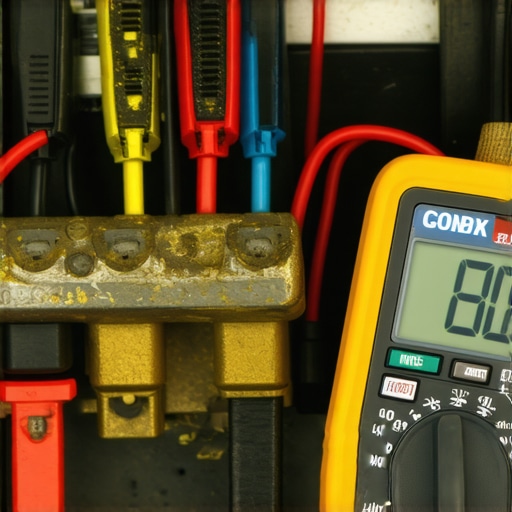
When cold weather strikes, your engine also demands significantly more amperage from the battery to overcome thickened engine oil during startup. If your terminal connections or ground paths are compromised, the high current demand will cause a massive voltage drop at the weak point, generating localized heat and starving your starter motor of the energy it needs to turn the engine over.
Why do lead-acid batteries suffer from internal sulfation during periods of low-voltage charging?
When a bad ground strap or a stretched battery terminal prevents the alternator from delivering a full charge, the battery remains in a chronic state of undercharge. This prolonged undercharged state initiates a chemical process known as sulfation, where amorphous lead sulfate converts into stable crystalline lead sulfate on the battery plates. According to technical documentation from the Battery Council International (BCI), these hardened crystals cannot be easily converted back into active material during standard charging cycles, permanently reducing the battery’s cold cranking amps (CCA) rating. Consistently maintaining robust, low-resistance connections is the single most effective way to prevent premature battery degradation and ensure your vehicle starts reliably in extreme weather.
The Critical Role of Fusible Links and High-Current Fuses in Circuit Protection
In your vehicle’s primary power distribution network, large-gauge wires handle raw power directly from the battery without the protection of standard cabin fuses. To prevent catastrophic electrical fires in the event of a direct short to ground, automotive engineers place high-current fuses or sacrificial wires called fusible links directly in line with these main power feeds. A fusible link is designed to safely melt and open the circuit when current exceeds its maximum rating, effectively acting as a structural weak point that protects the rest of the wiring harness.
However, when corrosion sneaks into the connections surrounding these high-current protection devices, the heat generated by the resistance can mimic a blown fuse or lead to intermittent power delivery. If you are experiencing total vehicle power loss but your battery and grounds test perfectly under load, inspecting the physical connections at the under-hood fuse box and verifying the integrity of the main fusible links is your next logical diagnostic step.
When troubleshooting modern multiplexed electrical networks, technicians often overlook the microscopic scale at which electrical degradation occurs. Micro-abrasions on terminal pins, invisible to the naked eye, can trigger fretting corrosion under standard driving vibrations. This physical phenomenon alters the circuit\’s impedance just enough to distort high-speed signal transmissions between the engine and transmission controllers, leading to erroneous diagnoses of failed physical components. Understanding these micro-level interactions prevents the unnecessary replacement of expensive sensors and modules.
Defeat the Invisible Creep of Terminal Fretting and Micro-Corrosion
Fretting corrosion occurs when thermal expansion and vehicle vibrations cause tiny, repetitive movements at the contact points of electrical connectors. These micro-slides wear away the protective tin or silver plating, exposing the underlying base metals to oxygen and moisture. The resulting microscopic debris pile-up behaves like a semi-conductor, introducing fluctuating resistance that directly interferes with low-voltage sensor communication lines. To combat this, precision diagnostic technicians use dedicated stabilizer compounds that seal out oxygen and electrically bridge the micro-gaps, ensuring clean communication paths without attracting abrasive road grime.
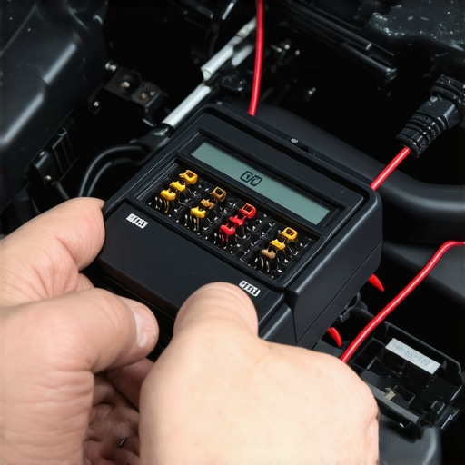
How do you diagnose high-resistance sensor circuits when a standard multimeter reads normal voltage?
A standard digital multimeter has an incredibly high input impedance, typically around 10 megohms. This means the meter itself draws virtually no current from the circuit during testing. Consequently, even if a sensor wire has microscopic corrosion that restricts active current flow, the open-circuit voltage will still read perfectly. To bypass this diagnostic trap, you must use an oscilloscope to capture real-time signal waveforms while active communication is occurring. A sudden voltage spike or a rounded, sluggish square wave on your scope screen immediately exposes hidden circuit resistance under load, pinpointing the problem wire long before a static voltmeter would show any deviation. Technical engineering papers from the Inter-Industry Conference on Auto Collision Repair (I-CAR) highlight that oscilloscope waveform analysis is the only definitive method for diagnosing high-speed network signal degradation.
The Critical Interplay of CAN Bus Signaling and Charging System Ripple
An often-ignored variable in persistent electrical gremlins is AC ripple voltage. Your vehicle\’s alternator generates alternating current, which is converted to direct current by an internal diode trio. When a single diode begins to fail, it leaks trace amounts of AC voltage into the direct-current system. While a standard battery might absorb some of this electrical noise, the high-frequency AC ripple disrupts the delicate digital signaling of the Controller Area Network (CAN bus). This electrical noise mimics the behavior of bad sensors or failing ground straps, generating a chaotic array of sporadic trouble codes across multiple vehicle modules. Testing for AC voltage at the battery terminals with the engine running is a vital step in isolating this hidden signal disruptor.
If you are ready to stop guessing and start diagnosing your vehicle\’s electrical anomalies with absolute precision, leave a comment below describing your most frustrating wiring mystery, and let\’s collaborate to resolve it using these expert-level testing methodologies.
Expert Insights & Advanced Considerations
High contact resistance degrades communication before melting fuses
Many technicians expect damaged wiring to immediately blow a fuse or melt a fusible link. However, high contact resistance restricts current and drops voltage dynamically while keeping the overall draw low enough to avoid tripping circuit protection. This creates a thermal bottleneck that cooks adjacent connectors without ever opening the fuse. This is why addressing the 15-battery-terminal-move-that-stops-mystery-no-start-issues is so vital to keeping your electronic control units stable and protected.
The alternator ripple effect corrupts local controller networks
When an internal diode leaks AC voltage into your 12V DC system, standard battery testers often miss the anomaly entirely. This high-frequency AC ripple acts as electromagnetic interference, corrupting the digital frame messages sent across the high-speed CAN bus network. If you are struggling with a cascade of unrelated sensor trouble codes, check for AC ripple before assuming you have physical module failures or bad wiring harnesses.
Oxidation acts as a microscopic semiconductor
At the physical level, thin layers of copper sulfate and lead oxide do not just resist current; they actually behave like crude diodes, allowing current to pass more easily in one direction than the other. This distortive physical property plays absolute havoc with low-voltage sensor return signals, which rely on precise millivolt references to calculate critical engine parameters.
Curated Expert Resources
The Society of Automotive Engineers (SAE) Technical Papers
This resource offers deep physical analyses of contact resistance, fretting corrosion, and electrical terminal degradation in automotive environments. It is indispensable for mastering low-voltage electrical circuit physics.
National Institute for Automotive Service Excellence (ASE) Study Guides
ASE preparation materials provide highly practical, real-world troubleshooting steps, emphasizing systematic voltage drop testing over static ohm measurements to save diagnostic time.
The Battery Council International (BCI) Technical Manuals
These manuals offer invaluable data regarding lead-acid battery chemistry, internal sulfation, charging profiles, and how high-resistance connections accelerate permanent battery capacity loss.
Final Expert Perspective
Chasing intermittent electrical gremlins can be incredibly daunting, but understanding the physics of voltage drops and ground path integrity transforms guesswork into a precise science. Most mystery blackouts and phantom trouble codes do not stem from blown computers or failed alternators, but rather from basic contact failures at battery terminals and chassis grounds. Making sure you know how to choose a skilled mechanic you can trust is your best defense against expensive, unnecessary parts-throwing when these complex issues arise. Have you successfully tracked down a stubborn ground issue or electrical bottleneck on your own vehicle? Join our community of DIY enthusiasts below to share your diagnostic strategies and tackle your toughest wiring questions together.