Avoid the Parts Cannon with a Simple Digital Multimeter
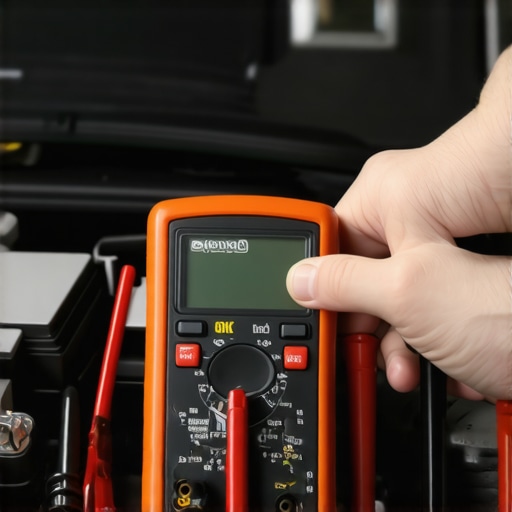
In the modern era of automotive maintenance, the impulse to immediately replace a battery or alternator at the first sign of a slow crank is a costly mistake. A seasoned mechanic knows that electrical diagnostics must begin with precise measurements rather than assumptions. While a comprehensive tune up usually focuses on spark plugs and filters, the charging system provides the lifeblood for every electronic control module in the vehicle. By utilizing a basic digital multimeter, you can perform a diagnostic routine that mirrors the rigorous standards of professional auto repair facilities, ensuring you don’t waste money on components that haven’t actually failed.
The first step in this analytical approach is verifying static versus surface charge. A battery resting at 12.6 volts is fully charged, but a reading of 12.2 volts indicates it is only at 50% capacity. However, the true test of a system’s health occurs under load. If you find your vehicle struggling, stop buying new batteries and check the resistance in your ground cables first. A high-resistance connection can mimic a dying battery, leading many DIYers to replace perfectly functional parts.
The Alternator Load Test Professionals Use
To truly evaluate the charging circuit, you must observe the voltage fluctuations while the engine is running. A healthy alternator should output between 13.5 and 14.7 volts. If the voltage remains near battery levels while the engine is idling, the internal voltage regulator or the brushes are likely compromised. You should be aware of the 5 ways your car tries to tell you the alternator is about to quit, as these signs often precede a total electrical collapse on the highway.
Expert-level diagnostics also involve checking for AC ripple. By switching your multimeter to AC voltage, you can detect if a diode in the alternator has failed, allowing alternating current to leak into the DC system. This “dirty” electricity can wreak havoc on sensitive sensors and even interfere with the computer logic governing your brake service alerts or transmission shift points. According to the Society of Automotive Engineers (SAE), maintaining a clean electrical signal is paramount for the longevity of modern vehicle networks.
Could a ghost drain be sabotaging your charging system overnight?
Even a perfect alternator cannot overcome a parasitic draw that depletes the battery while the ignition is off. If your car is dead every morning, you may be dealing with the hidden battery drain that kills cars overnight. By placing your multimeter in series (Amps mode) between the negative terminal and the cable, you can identify which circuit is refusing to go to sleep. This methodical isolation is exactly how a top-rated mechanic ensures safe auto repairs every time, preventing the frustration of a recurring “no-start” condition.
If you have identified a complex electrical fault that goes beyond basic wiring, consider consulting a specialist to prevent further damage to your vehicle’s ECU. We invite you to share your diagnostic findings or ask specific technical questions in our community forum to further refine your automotive expertise.
Look Beyond the Gearbox When Shifting Gets Weird
Many drivers assume that a transmission hunting for gears or a sudden ‘hard shift’ indicates a mechanical failure deep within the planetary gears or clutch packs. However, experienced technicians often look for electrical interference before suggesting a teardown. Modern transmissions rely on solenoid packs that are highly sensitive to voltage fluctuations. If your vehicle feels indecisive on the highway, it might not be a mechanical slip; you could be experiencing the 14 dollar ground strap that fixes ghost shifting and restores smooth operation. When a ground connection corrodes, it creates electrical noise that confuses the transmission control module, causing it to command shifts at the wrong hydraulic pressure levels.
This same logic applies to mysterious engine hesitations. A weak electrical return path can cause sensors to send erratic data to the ECU. If you have been chasing a rough idle without success, consider that the 12 dollar ground wire that fixes stalling issues might be the missing piece of your diagnostic puzzle. By ensuring the engine block, chassis, and battery are at the same electrical potential, you eliminate the resistance that throttles your car’s performance.

Why High-Tech Brake Systems Demand Pristine Voltage
Modern brake service is no longer just about friction material and hydraulic fluid. Anti-lock Braking Systems (ABS) and Electronic Stability Control (ESC) are essentially computer networks on wheels. These systems perform thousands of self-checks per second, and a momentary drop in voltage can trigger a dashboard warning light or, worse, a hard brake pedal. If you notice that why your brake pedal feels hard as a rock happens sporadically, the culprit might be an electrical supply issue to the brake booster pump rather than a vacuum leak. High-quality diagnostics ensure you are applying brake service secrets how to boost safety and longevity by maintaining the electronic integrity of the stopping system.
According to technical specifications from Bosch Automotive, many ABS sensors require a stable reference voltage of exactly 5.0 volts to function correctly. Even a minor deviation caused by a failing alternator diode can lead to ‘phantom’ ABS activations, which can be dangerous during emergency maneuvers. Ensuring your auto repair strategy includes a deep dive into the wiring harness can save hundreds of dollars in unnecessary module replacements.
Is your car’s brain actually starving for current?
When multiple warning lights illuminate simultaneously—often called the ‘Christmas tree effect’—it is rarely a sign that five different mechanical systems failed at once. Instead, it is the primary indicator that the central processing unit is starving for stable current. This often occurs when a DIYer neglects a tune up of the battery terminals. A thin layer of lead sulfate on the posts creates enough resistance to drop the voltage during high-demand moments, such as when the cooling fans kick on or the AC compressor engages. Before you commit to expensive sensor replacements, use your multimeter to check for voltage drops across the main fuse box. We would love to hear about the most baffling electrical gremlin you’ve ever solved; leave a comment below with your diagnostic story to help fellow enthusiasts skip the ‘parts cannon’ and get straight to the fix.
Data Packets Drown When Your Charging System Gets Noisy
As we transition from simple electrical circuits to complex Controller Area Networks (CAN), the margin for error in voltage stability has narrowed to almost zero. In a modern vehicle, the alternator doesn’t just charge the battery; it provides the baseline frequency for a symphony of data. When a diode begins to leak even a small amount of alternating current, it creates ‘electrical noise’ that can corrupt the binary messages traveling between your engine and transmission. While a tune up used to focus on mechanical timing, today’s auto repair requires an understanding of signal integrity. If you are seeing ‘U’ prefix codes (network communication codes) on your scanner, don’t rush to replace expensive modules. Often, the root cause is a ripple voltage exceeding 50mV, which effectively ‘yells’ over the digital whispers of the vehicle’s computer modules.
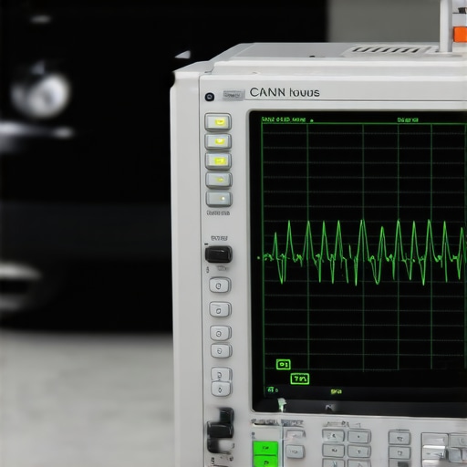
According to the ISO 11898 standard, which governs road vehicle controller area networks, the differential voltage between CAN-High and CAN-Low must remain within strict tolerances to ensure data reliability. A failing voltage regulator can cause micro-spikes that mimic a failed sensor, leading many to fire the parts cannon at a perfectly healthy throttle body or mass airflow sensor. To truly master auto repair, you must learn to see the electricity, not just measure its presence. For those looking to dive deeper into these digital mysteries, we recommend checking out our guide on isolating bus interference before you start unpinning harnesses.
Can a digital multimeter give you a ‘ghost’ reading on a dead circuit?
One of the most frustrating traps for DIYers and even some professionals is the ‘ghost voltage’ phenomenon. High-impedance digital multimeters are so sensitive that they can pick up voltage through induction from an adjacent wire, even if the circuit you are testing is completely broken. You might see 12 volts on your screen and assume the circuit is live, but the moment you add a load—like a bulb or a motor—the voltage drops to zero. This happens because there is no ‘current’ (amps) to back up the ‘pressure’ (volts). To combat this, experienced technicians often use a ‘test light’ or a ‘loaded multimeter’ (LoZ mode) to ensure the wire can actually do work. This distinction is vital during a complex brake service involving electronic parking brakes, where a wire might show voltage but fail to provide the amperage needed to move the caliper motor.
Stop Trusting Your Continuity Beep for High-Load Circuits
The ‘beep’ of a multimeter’s continuity setting is perhaps the most overused and misunderstood tool in the mechanic’s arsenal. A single strand of copper wire in a harness of twenty can trigger a continuity beep, but that single strand cannot carry the 15 or 20 amps required for a fuel pump or cooling fan. This is where voltage drop testing becomes the gold standard of auto repair. By measuring the voltage lost across a connection while the circuit is ‘on’ and working, you expose the resistance that static tests miss. If you lose more than 0.2 volts across a connector, you’ve found a bottleneck that a simple tune up won’t fix. Consider the fuel system: a small amount of resistance in the pump’s power feed can reduce its RPM just enough to cause a lean condition under wide-open throttle, yet the pump will still ‘run’ and pass a basic bench test.
When you start analyzing current ramping—measuring the actual ‘shape’ of the amperage as a motor turns—you begin to see mechanical problems through an electrical lens. For example, a fuel pump with a worn commutator will show a ‘jagged’ amperage wave on an oscilloscope long before it actually dies. This proactive diagnostic style allows you to catch failures during a routine service rather than on the side of a busy highway. If you’ve ever been stumped by a pump that only fails when it’s hot, you’re likely dealing with internal thermal expansion that increases resistance beyond the threshold of the pump’s relay…
Stop Squinting at Volts and Start Mapping Amperage Waves
The limitations of a standard digital multimeter become glaringly apparent when dealing with Pulse Width Modulation (PWM) signals. In many modern vehicles, the mechanic is no longer looking at a steady 12-volt supply for components like cooling fans, fuel pumps, or even headlight assemblies. Instead, the ECU switches the ground on and off thousands of times per second to vary speed, torque, or brightness. A multimeter will average this rapid-fire signal, giving you a ‘phantom’ reading of 6 or 9 volts, which might lead an inexperienced technician to believe there is a wiring fault or a failing relay. To truly verify the health of these circuits during a tune up, you must employ a lab scope to visualize the duty cycle and frequency in real-time. This is the difference between a guess and a guarantee in professional auto repair, where precision is the only path to a permanent fix.
Why does your brand-new alternator fail the bench test at the auto parts store?
Many DIYers and even entry-level technicians are baffled when a replacement alternator fails immediately or won’t charge despite being ‘tested’ at the store. The answer lies in the complexity of modern LIN-bus and CAN-bus communication. According to technical documentation from Delphi Technologies, many late-model alternators are ‘smart’; they do not output voltage unless they receive a specific digital command from the Engine Control Unit (ECU). A standard bench tester cannot replicate this encrypted handshake. If the ECU doesn’t see the correct battery temperature or current demand via the Intelligent Battery Sensor (IBS), it may command the alternator to remain in a ‘fuel-saving’ mode, which a novice might misinterpret as a charging system failure during a routine brake service or inspection.
Thermal Imaging Exposes the Resistance Your Multimeter Misses
Resistance creates heat, a physical law that the infrared camera exploits to save you hours of teardown. By using a high-resolution infrared camera, you can scan a junction block, a battery cable, or a relay center while the system is under load. A corroded terminal or a loose ground that looks perfect to the naked eye will glow brightly on the thermal screen, revealing a bottleneck that is strangling the vehicle’s electrical performance. This non-invasive technique is particularly effective when troubleshooting those ‘intermittent’ failures that only occur after the vehicle has reached operating temperature. It allows for a level of precision that traditional auto repair methods simply cannot match, ensuring every tune up addresses the invisible hurdles within the wiring harness before they leave you stranded.
Smart Charging Demands a Specialized Strategy
When a vehicle features an AGM (Absorbent Glass Mat) battery, the charging strategy is significantly more aggressive than with traditional flooded lead-acid units. If you replace an AGM battery without ‘registering’ the new part with the vehicle’s computer, the alternator will continue to charge at the higher voltage levels required for an aged battery, effectively ‘cooking’ the new unit within months. This highlights why a professional brake service or mechanical overhaul must always be paired with a digital system reset using a high-end scan tool. We encourage you to download our advanced diagnostic checklist to ensure your next project meets these rigorous OEM standards and avoids the pitfalls of ‘smart’ system mismanagement.
Avoid the Parts Cannon with a Simple Digital Multimeter
In the modern era of automotive maintenance, the impulse to immediately replace a battery or alternator at the first sign of a slow crank is a costly mistake. A seasoned mechanic knows that electrical diagnostics must begin with precise measurements rather than assumptions. While a comprehensive tune up usually focuses on spark plugs and filters, the charging system provides the lifeblood for every electronic control module in the vehicle. By utilizing a basic digital multimeter, you can perform a diagnostic routine that mirrors the rigorous standards of professional auto repair facilities, ensuring you don’t waste money on components that haven’t actually failed.
The first step in this analytical approach is verifying static versus surface charge. A battery resting at 12.6 volts is fully charged, but a reading of 12.2 volts indicates it is only at 50% capacity. However, the true test of a system’s health occurs under load. If you find your vehicle struggling, stop buying new batteries and check the resistance in your ground cables first. A high-resistance connection can mimic a dying battery, leading many DIYers to replace perfectly functional parts.
The Alternator Load Test Professionals Use
To truly evaluate the charging circuit, you must observe the voltage fluctuations while the engine is running. A healthy alternator should output between 13.5 and 14.7 volts. If the voltage remains near battery levels while the engine is idling, the internal voltage regulator or the brushes are likely compromised. You should be aware of the 5 ways your car tries to tell you the alternator is about to quit, as these signs often precede a total electrical collapse on the highway.
Expert-level diagnostics also involve checking for AC ripple. By switching your multimeter to AC voltage, you can detect if a diode in the alternator has failed, allowing alternating current to leak into the DC system. This “dirty” electricity can wreak havoc on sensitive sensors and even interfere with the computer logic governing your brake service alerts or transmission shift points. According to the Society of Automotive Engineers (SAE), maintaining a clean electrical signal is paramount for the longevity of modern vehicle networks.
Could a ghost drain be sabotaging your charging system overnight?
Even a perfect alternator cannot overcome a parasitic draw that depletes the battery while the ignition is off. If your car is dead every morning, you may be dealing with the hidden battery drain that kills cars overnight. By placing your multimeter in series (Amps mode) between the negative terminal and the cable, you can identify which circuit is refusing to go to sleep. This methodical isolation is exactly how a top-rated mechanic ensures safe auto repairs every time, preventing the frustration of a recurring “no-start” condition.
If you have identified a complex electrical fault that goes beyond basic wiring, consider consulting a specialist to prevent further damage to your vehicle’s ECU. We invite you to share your diagnostic findings or ask specific technical questions in our community forum to further refine your automotive expertise.
Look Beyond the Gearbox When Shifting Gets Weird
Many drivers assume that a transmission hunting for gears or a sudden ‘hard shift’ indicates a mechanical failure deep within the planetary gears or clutch packs. However, experienced technicians often look for electrical interference before suggesting a teardown. Modern transmissions rely on solenoid packs that are highly sensitive to voltage fluctuations. If your vehicle feels indecisive on the highway, it might not be a mechanical slip; you could be experiencing the 14 dollar ground strap that fixes ghost shifting and restores smooth operation. When a ground connection corrodes, it creates electrical noise that confuses the transmission control module, causing it to command shifts at the wrong hydraulic pressure levels.
This same logic applies to mysterious engine hesitations. A weak electrical return path can cause sensors to send erratic data to the ECU. If you have been chasing a rough idle without success, consider that the 12 dollar ground wire that fixes stalling issues might be the missing piece of your diagnostic puzzle. By ensuring the engine block, chassis, and battery are at the same electrical potential, you eliminate the resistance that throttles your car’s performance.
Why High-Tech Brake Systems Demand Pristine Voltage
Modern brake service is no longer just about friction material and hydraulic fluid. Anti-lock Braking Systems (ABS) and Electronic Stability Control (ESC) are essentially computer networks on wheels. These systems perform thousands of self-checks per second, and a momentary drop in voltage can trigger a dashboard warning light or, worse, a hard brake pedal. If you notice that why your brake pedal feels hard as a rock happens sporadically, the culprit might be an electrical supply issue to the brake booster pump rather than a vacuum leak. High-quality diagnostics ensure you are applying brake service secrets how to boost safety and longevity by maintaining the electronic integrity of the stopping system.
According to technical specifications from Bosch Automotive, many ABS sensors require a stable reference voltage of exactly 5.0 volts to function correctly. Even a minor deviation caused by a failing alternator diode can lead to ‘phantom’ ABS activations, which can be dangerous during emergency maneuvers. Ensuring your auto repair strategy includes a deep dive into the wiring harness can save hundreds of dollars in unnecessary module replacements.
Is your car’s brain actually starving for current?
When multiple warning lights illuminate simultaneously—often called the ‘Christmas tree effect’—it is rarely a sign that five different mechanical systems failed at once. Instead, it is the primary indicator that the central processing unit is starving for stable current. This often occurs when a DIYer neglects a tune up of the battery terminals. A thin layer of lead sulfate on the posts creates enough resistance to drop the voltage during high-demand moments, such as when the cooling fans kick on or the AC compressor engages. Before you commit to expensive sensor replacements, use your multimeter to check for voltage drops across the main fuse box. We would love to hear about the most baffling electrical gremlin you’ve ever solved; leave a comment below with your diagnostic story to help fellow enthusiasts skip the ‘parts cannon’ and get straight to the fix.
Data Packets Drown When Your Charging System Gets Noisy
As we transition from simple electrical circuits to complex Controller Area Networks (CAN), the margin for error in voltage stability has narrowed to almost zero. In a modern vehicle, the alternator doesn’t just charge the battery; it provides the baseline frequency for a symphony of data. When a diode begins to leak even a small amount of alternating current, it creates ‘electrical noise’ that can corrupt the binary messages traveling between your engine and transmission. While a tune up used to focus on mechanical timing, today’s auto repair requires an understanding of signal integrity. If you are seeing ‘U’ prefix codes (network communication codes) on your scanner, don’t rush to replace expensive modules. Often, the root cause is a ripple voltage exceeding 50mV, which effectively ‘yells’ over the digital whispers of the vehicle’s computer modules.
According to the ISO 11898 standard, which governs road vehicle controller area networks, the differential voltage between CAN-High and CAN-Low must remain within strict tolerances to ensure data reliability. A failing voltage regulator can cause micro-spikes that mimic a failed sensor, leading many to fire the parts cannon at a perfectly healthy throttle body or mass airflow sensor. To truly master auto repair, you must learn to see the electricity, not just measure its presence. For those looking to dive deeper into these digital mysteries, we recommend checking out our guide on isolating bus interference before you start unpinning harnesses.
Can a digital multimeter give you a ‘ghost’ reading on a dead circuit?
One of the most frustrating traps for DIYers and even some professionals is the ‘ghost voltage’ phenomenon. High-impedance digital multimeters are so sensitive that they can pick up voltage through induction from an adjacent wire, even if the circuit you are testing is completely broken. You might see 12 volts on your screen and assume the circuit is live, but the moment you add a load—like a bulb or a motor—the voltage drops to zero. This happens because there is no ‘current’ (amps) to back up the ‘pressure’ (volts). To combat this, experienced technicians often use a ‘test light’ or a ‘loaded multimeter’ (LoZ mode) to ensure the wire can actually do work. This distinction is vital during a complex brake service involving electronic parking brakes, where a wire might show voltage but fail to provide the amperage needed to move the caliper motor.
Stop Trusting Your Continuity Beep for High-Load Circuits
The ‘beep’ of a multimeter’s continuity setting is perhaps the most overused and misunderstood tool in the mechanic’s arsenal. A single strand of copper wire in a harness of twenty can trigger a continuity beep, but that single strand cannot carry the 15 or 20 amps required for a fuel pump or cooling fan. This is where voltage drop testing becomes the gold standard of auto repair. By measuring the voltage lost across a connection while the circuit is ‘on’ and working, you expose the resistance that static tests miss. If you lose more than 0.2 volts across a connector, you’ve found a bottleneck that a simple tune up won’t fix. Consider the fuel system: a small amount of resistance in the pump’s power feed can reduce its RPM just enough to cause a lean condition under wide-open throttle, yet the pump will still ‘run’ and pass a basic bench test.
When you start analyzing current ramping—measuring the actual ‘shape’ of the amperage as a motor turns—you begin to see mechanical problems through an electrical lens. For example, a fuel pump with a worn commutator will show a ‘jagged’ amperage wave on an oscilloscope long before it actually dies. This proactive diagnostic style allows you to catch failures during a routine service rather than on the side of a busy highway. If you’ve ever been stumped by a pump that only fails when it’s hot, you’re likely dealing with internal thermal expansion that increases resistance beyond the threshold of the pump’s relay…
Stop Squinting at Volts and Start Mapping Amperage Waves
The limitations of a standard digital multimeter become glaringly apparent when dealing with Pulse Width Modulation (PWM) signals. In many modern vehicles, the mechanic is no longer looking at a steady 12-volt supply for components like cooling fans, fuel pumps, or even headlight assemblies. Instead, the ECU switches the ground on and off thousands of times per second to vary speed, torque, or brightness. A multimeter will average this rapid-fire signal, giving you a ‘phantom’ reading of 6 or 9 volts, which might lead an inexperienced technician to believe there is a wiring fault or a failing relay. To truly verify the health of these circuits during a tune up, you must employ a lab scope to visualize the duty cycle and frequency in real-time. This is the difference between a guess and a guarantee in professional auto repair, where precision is the only path to a permanent fix.
Why does your brand-new alternator fail the bench test at the auto parts store?
Many DIYers and even entry-level technicians are baffled when a replacement alternator fails immediately or won’t charge despite being ‘tested’ at the store. The answer lies in the complexity of modern LIN-bus and CAN-bus communication. According to technical documentation from Delphi Technologies, many late-model alternators are ‘smart’; they do not output voltage unless they receive a specific digital command from the Engine Control Unit (ECU). A standard bench tester cannot replicate this encrypted handshake. If the ECU doesn’t see the correct battery temperature or current demand via the Intelligent Battery Sensor (IBS), it may command the alternator to remain in a ‘fuel-saving’ mode, which a novice might misinterpret as a charging system failure during a routine brake service or inspection.
Thermal Imaging Exposes the Resistance Your Multimeter Misses
Resistance creates heat, a physical law that the infrared camera exploits to save you hours of teardown. By using a high-resolution infrared camera, you can scan a junction block, a battery cable, or a relay center while the system is under load. A corroded terminal or a loose ground that looks perfect to the naked eye will glow brightly on the thermal screen, revealing a bottleneck that is strangling the vehicle’s electrical performance. This non-invasive technique is particularly effective when troubleshooting those ‘intermittent’ failures that only occur after the vehicle has reached operating temperature. It allows for a level of precision that traditional auto repair methods simply cannot match, ensuring every tune up addresses the invisible hurdles within the wiring harness before they leave you stranded.
Smart Charging Demands a Specialized Strategy
When a vehicle features an AGM (Absorbent Glass Mat) battery, the charging strategy is significantly more aggressive than with traditional flooded lead-acid units. If you replace an AGM battery without ‘registering’ the new part with the vehicle’s computer, the alternator will continue to charge at the higher voltage levels required for an aged battery, effectively ‘cooking’ the new unit within months. This highlights why a professional brake service or mechanical overhaul must always be paired with a digital system reset using a high-end scan tool. We encourage you to download our advanced diagnostic checklist to ensure your next project meets these rigorous OEM standards and avoids the pitfalls of ‘smart’ system mismanagement.
Expert Perspectives on High-Level Electrical Diagnostics
The Invisible Wall of Ground Offset Resistance
Technicians often forget that a multimeter reading is only as good as the reference point. Ground offset occurs when the chassis ground and the engine block ground differ by more than 50mV. This subtle gap can shift the entire signal range of an oxygen sensor or a throttle position sensor, leading a mechanic to chase ghosts in the fuel map when the actual problem is a oxidized bolt. Always bridge your negative probe to the actual battery post to establish a true zero-point before trusting any sensor reading.
Why Module Sleep Cycles Ruin Quick Diagnostics
In the world of auto repair, patience is a diagnostic tool. Modern Luxury vehicles can take up to 45 minutes for every module to enter ‘sleep’ mode. If you attempt to measure parasitic draw too early, you will see a massive amp pull and potentially condemn a perfectly healthy Body Control Module. Real expertise lies in understanding the handshake protocols that occur after the key is removed, ensuring you aren’t fighting a system that is simply doing its job.
Stop Believing Your Dash Voltmeter is Accurate
Most instrument cluster voltmeters are heavily dampened by software to prevent the needle from jumping during normal regulation. They are essentially ‘dummy lights’ in gauge form. By the time your dashboard displays a low-voltage warning, the system has likely been failing for days. Relying on these gauges for a performance tune up is a recipe for disaster; only a direct-at-battery measurement with a calibrated tool provides the truth.
Curated Expert Resources
ScannerDanner (Paul Danner) Diagnostic Guides: Paul Danner is widely considered the gold standard for teaching electrical theory to the modern mechanic. His focus on ‘testing, not guessing’ provides the mathematical foundation needed to solve complex engine performance issues without unnecessary parts replacement.
Automotive Electronics Council (AEC) Component Standards: For those looking to understand why certain sensors fail under heat or vibration, the AEC provides the rigorous stress-test protocols that original equipment manufacturers (OEMs) use to qualify automotive-grade semiconductors.
Battery Council International (BCI) Technical Manuals: This is the definitive source for understanding battery chemistry and the specific charging profiles required for modern AGM and Enhanced Flooded Batteries (EFB). It is essential reading for anyone performing a high-level tune up on start-stop equipped vehicles.
Final Expert Perspective
Navigating the complex electrical architecture of modern vehicles requires a shift in mindset from mechanical logic to signal integrity. Whether you are performing a routine tune up or a critical brake service, the success of the repair depends entirely on the stability of the voltage reaching the control modules. A skilled mechanic understands that the “parts cannon” is a symptom of incomplete data. By mastering the nuances of AC ripple, pulse-width modulation, and ground offsets, you elevate your auto repair capability from basic maintenance to expert-level restoration. We invite you to join our professional network and share your most challenging diagnostic breakthroughs; your unique experience could be the key that helps a fellow technician solve an impossible electrical mystery. If you want to learn how a top-rated mechanic ensures safe auto repairs every time, it starts with the data provided by your multimeter.