Why Modern Electrical Parasitic Draws Confound Traditional Diagnostics
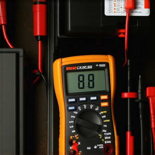
Vehicles today operate on complex, interconnected multiplexed networks. When you turn off the ignition, dozens of Electronic Control Units (ECUs) do not sleep immediately; they undergo a structured, multi-stage shutdown sequence. A single module remaining awake—whether it is an infotainment controller or a body control unit—can pull upwards of 500 milliamperes, quietly draining your starting battery overnight. Traditional test lights are no longer sufficient for diagnosing these issues, as introducing them can spike the current and wake up sleeping modules. To successfully troubleshoot modern electrical systems, drivers and DIY mechanics must rely on scientific, non-intrusive diagnostic protocols to isolate parasitic loads without interrupting the vehicle’s electrical state.
The Mathematical Reality of Voltage Drop Testing Across Fuses
Using a standard digital multimeter, automotive specialists utilize a highly reliable method known as the voltage drop test. Instead of pulling fuses—which can temporarily reset a malfunctioning module and mask the fault—you measure the minute millivolt drop across the top of a fuse while it remains in the fuse block. This technique relies on Ohm’s Law, where the fuse element itself acts as a known, precision resistor. By checking the millivolt reading against standard fuse manufacturer charts, you can determine the exact current draw in milliamperes. For a comprehensive overview of how small components can trigger catastrophic failures, read our guide on how to stop throwing parts at your P0420 code and verify basic components first.
How do you differentiate between a normal module sleep cycle and a genuine parasitic drain?
Distinguishing a normal, temporary module delay from a true fault requires patience and strict timing. Most modern vehicles require anywhere from 20 to 60 minutes to enter a complete ‘sleep’ state. To perform an accurate diagnosis, you must simulate a locked, parked vehicle by latching the door switches manually while keeping the doors open. This provides direct access to the interior fuse panels without waking the computer networks. If your multimeter detects a current draw exceeding 50 milliamperes after one hour of idle time, you are dealing with a parasitic drain rather than a standard system cooldown. To build your automotive diagnostic toolkit, consult our resource on mechanic tips for diagnosing common auto problems.
Isolate the Circuit with Precision Before Replacing Components
Once you identify the specific fuse exhibiting a voltage drop, you can trace the circuit diagram to pinpoint the failing load. For instance, a continuous draw on the radio circuit often points to an aftermarket accessory wired incorrectly or a stuck internal relay. Making assumptions about components without systematic testing is a common pitfall that leads to unnecessary parts replacement. For those looking to master DIY maintenance and reduce repair bills, exploring auto repair cost-saving tips from industry experts can prevent costly misdiagnoses. According to the National Institute for Automotive Service Excellence (ASE), structured electrical diagnostic procedures save vehicle owners hundreds of dollars annually in unnecessary battery and alternator replacements.
Exposing the Faulty Ground Strap Trap
Many diagnostic procedures stop once a suspicious fuse is isolated, but seasoned technicians know that the root cause of electrical misbehavior often lies on the return path of the circuit. A loose, corroded, or degraded engine ground strap can elevate circuit resistance, forcing current to seek alternative, unintended paths to the chassis. This phenomenon can easily mimic an active parasitic draw or create random, intermittent control module resets. When a ground connection is compromised, the voltage drop across that junction rises, leading to mysterious sensor errors and starting issues. To prevent yourself from chasing ghosts, performing a quick resistance and voltage drop test between the engine block and the negative battery terminal is essential. For resolving these baffling issues directly, look into the 15 ground strap fix for mystery electrical gremlins to restore solid electrical continuity.
Why Aftermarket Accessories Break OEM Sleep Protocols
The modern automotive ecosystem is finely tuned, and aftermarket additions are the most common disruptors of this delicate balance. Remote starters, dash cams, and upgraded infotainment systems are frequently spliced into constant power sources rather than accessory circuits. Even when wired to an ignition-switched source, poorly designed aftermarket modules can generate electrical noise on the Controller Area Network (CAN bus). This high-frequency noise prevents the vehicle’s primary Body Control Module (BCM) from issuing the final ‘go to sleep’ command to other nodes. Consequently, multiple factory modules stay active, compounding the total electrical drain. If you have recently installed any non-factory electronics, they should be the absolute first components you isolate during your troubleshooting process.
What happens when a failing alternator diode mimics a dead battery?
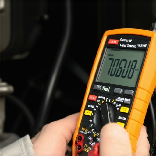
An often overlooked source of overnight battery drain is a bad rectifier diode inside the alternator. Diodes act as one-way electrical valves, converting alternating current (AC) produced by the alternator into the direct current (DC) your car’s electrical system requires. When one of these diodes fails or leaks, it can allow current to flow backward through the alternator winding even when the engine is completely off. This creates an internal loop that silently drains your battery without routing through any of the fuses in your cabin or engine bay fuse blocks. To rule this out, you can measure AC voltage at the battery terminals while the engine is running, or simply test for a warm alternator housing after the vehicle has sat idle for several hours. For deeper insight into diagnosing charging system health before investing in expensive replacements, read our detailed guide on the 10 multimeter trick for spotting a dying alternator before it strands you.
The Thermal Imaging Shortcut for Finding Hidden Hotspots
While voltage drop testing across fuses is highly accurate, advanced shops increasingly utilize thermal imaging cameras to expedite the diagnostic process. Because electrical current naturally generates heat, any circuit pulling a persistent parasitic draw will be slightly warmer than the surrounding inactive circuits. By scanning the vehicle’s fuse boxes and wiring harnesses with an infrared camera after the vehicle has rested for an hour, you can instantly identify warm fuses or modules glowing on the screen. This non-contact visual approach bypasses the tedious process of manual probing and is especially useful for locating shorts in deeply buried wiring harnesses. According to the Society of Automotive Engineers (SAE), integrating thermographic inspection into electrical troubleshooting reduces diagnostic time by up to forty percent for complex multiplexed networks. Have you encountered a persistent battery drain that defied standard troubleshooting? Leave a comment below or share this guide with a fellow DIYer to help them save time and avoid throwing unnecessary parts at their vehicle.
Why Multiplexed CAN Bus Lines Refuse to Sleep
Modern vehicles rely on Controller Area Network (CAN) bus lines to transmit hundreds of signals per second between control modules. When troubleshooting a stubborn battery drain, you must understand that these communication lines operate on tiny voltage differentials. A single pinched wire, wet door latch switch, or corroded connector can cause high-frequency electrical reflection on the CAN bus. This constant digital chatter prevents the network from transitioning into its low-power standby mode. Instead of a single module causing the draw, the entire network remains awake, consuming several amperes of current. To isolate a talking module without disconnecting the battery and erasing vital diagnostic trouble codes, you should monitor the activity on CAN-High and CAN-Low lines using a specialized automotive oscilloscope.
How do you safely isolate a gateway module without triggering a system-wide network wake-up?
Isolating a central gateway module requires a systematic approach known as selective node isolation. You cannot simply unplug the gateway, as doing so breaks the communication loop and causes remaining modules to enter an error state, keeping them permanently awake. The correct procedure involves using a breakout box connected to the OBD-II diagnostic port to monitor terminal resistance across pins 6 and 14. By carefully disconnecting individual branch connectors at the star splice pack, you can watch for the instant the network resistance shifts back to the standard 60 ohms. This tells you exactly which branch of the multiplex network is harboring the rogue module keeping the vehicle’s system active.

Advanced Oscilloscope Diagnostics for Transient Current Spikes
Some parasitic draws are not constant; they manifest as intermittent, transient current spikes that occur hours after the vehicle is locked. A standard digital multimeter is too slow to capture these microsecond events, often averaging the readings and hiding the spike. An automotive lab scope equipped with a low-amp current probe is the ultimate tool for these situations. By clamping the probe around the negative battery cable and setting the scope to record on a slow sweep, you can capture long-term electrical signatures. This allows you to visualize the exact moment a module unexpectedly wakes up, performs an action, and fails to shut down. Analyzing the shape and frequency of these current waveforms can point directly to mechanical sticking inside an actuator or a internal software loop lockup.
While capturing transient current spikes reveals the signature of a rogue module, pinpointing the physical location of the wiring fault requires moving beyond simple signal logging. When a lab scope exposes recurring electrical spikes, it is often a symptom of capacitive coupling or physical insulation degradation somewhere along the wiring harness. This is especially true in vehicles subjected to harsh winters, where road salt and moisture can bridge connector pins, creating high-resistance short circuits that bypass standard fuses entirely. Technicians must understand that these micro-amperage leaks can bypass the central junction box, routing power through moisture-logged wiring channels directly to ground.
Why Water Intrusion in Kick Panel Connectors Mimics Module Failure
A common mistake during advanced diagnostics is condemning an expensive Body Control Module when the actual culprit is a corroded inline connector hidden beneath the vehicle’s carpeting. Water tracking down the A-pillar wiring harness frequently pools in the kick panel connectors, creating a bridging path between constant battery feed lines and low-voltage communication lines. This wet bridge allows a minute amount of current to bleed continually into the communication bus, simulating an active node that refuses to sleep. To confirm this without tearing apart the interior, you can perform a pin-by-pin resistance check at the central gateway connector relative to chassis ground, looking for any value below 10,000 ohms on non-ground circuits. For professional technicians looking to refine their systematic approach to complex vehicle networks, referencing the detailed training guidelines provided by the International Automotive Technicians Network (iATN) is highly recommended.
What is the safest way to trace a short to ground without blowing replacement fuses?
To safely trace a short to ground without repeatedly blowing fuses or risking damage to delicate harness wiring, you should replace the blown fuse with a dynamic test light or a dedicated short-circuit finder. By connecting a high-wattage test light directly across the open fuse terminals, the light will illuminate brightly as long as the short to ground exists, acting as a safe current limiter for the circuit. You can then systematically wiggle the wiring harness at key stress points, such as door hinges, firewall pass-throughs, and tight bends. The moment the test light flickers or goes out, you have isolated the exact physical location of the chafed wire, allowing you to perform a permanent solder repair and heat-shrink insulation restoration.
The Critical Step of Verifying Current Flow Directions
When working with complex multiplexed layouts, diagnosing a parasitic draw without analyzing the direction of current flow can lead to frustrating dead ends. Using a directional DC clamp-on amp meter allows you to determine whether current is flowing out of a module or feeding back into it from an external short circuit. This distinction is vital; a module drawing power is the source of the issue, whereas a module receiving back-fed power is merely a victim of a bridged harness elsewhere. Have you ever spent hours chasing an elusive electrical ghost only to find a simple pinched wire? Join our community of diagnostic enthusiasts by dropping a comment below with your most challenging electrical repair stories.
Expert Insights & Advanced Considerations
Oscilloscopes Reveal What Digital Multimeters Conceal
While a high-quality multimeter is indispensable for measuring static voltage drops, it lacks the sampling rate necessary to capture transient communication spikes on a multiplexed bus. When a gateway module briefly wakes up and transmits corrupt data packets before returning to standby, only an automotive lab scope can capture the resulting milliampere waveform. Technicians should monitor these high-speed transitions to identify internal module software hangs. For drivers looking to expand their fundamental diagnostic skills before diving into advanced waveforms, reviewing our guide on mechanic tips for diagnosing common auto problems is an excellent starting point.
Water Pools in Kick Panels Long Before Modules Fail
Corrosion within low-lying wiring harnesses often masquerades as a failed module. Water tracking down the A-pillar can pool in the kick panel inline connectors, bridging the gap between constant battery power and sensitive communication lines. This wet bridge keeps the CAN bus active, causing massive parasitic draws. Before condemning an expensive body control unit, perform a physical inspection of these connectors. Understanding these hidden failures is a key part of smart DIY vehicle ownership; you can explore other highly effective auto repair cost-saving tips from industry experts to keep your diagnostic path both logical and affordable.
Why Poor Ground Paths Create Phantom Parasitic Loads
An elevated ground resistance forces electrical current to seek alternative return paths through adjacent circuits. This phenomenon can keep delicate solid-state relays partially energized, resulting in a persistent, low-level drain that vanishes when the battery is disconnected for testing. To eliminate these confounding variables, a quick voltage drop test on the primary engine ground is vital. If you suspect your vehicle is suffering from unstable chassis grounds or mysterious control module resets, implementing the 15 ground strap fix for mystery electrical gremlins can quickly stabilize your entire multiplex network.
Curated Expert Resources
International Automotive Technicians Network (iATN): A peer-to-peer network offering an unmatched database of real-world repair stories and vehicle-specific scope waveforms uploaded by master diagnostic specialists.
Society of Automotive Engineers (SAE) Technical Papers: The absolute authority on CAN bus protocols and OEM sleep cycle specifications, ideal for technicians seeking to understand the physics of signal reflection and network termination.
National Institute for Automotive Service Excellence (ASE) Study Guides: Essential resources for mastering systematic electrical troubleshooting methodologies, ensuring your diagnostic steps remain logical, safe, and efficient.
Final Expert Perspective
Diagnosing a complex automotive electrical system requires moving beyond guesswork and component-swapping. To successfully identify a modern automotive parasitic draw, you must respect the communication protocols of multiplexed networks and use systematic, non-intrusive testing methods like voltage drop measurements and circuit isolation. When you approach electrical anomalies with scientific rigor, you save time, avoid misdiagnoses, and prevent damage to expensive onboard computers. To further elevate your diagnostic capabilities and keep your vehicle operating at peak efficiency, read our guide on essential tune-up tips to boost your cars performance in 2025. We invite you to share your most challenging electrical diagnostic stories in the comments section below to collaborate with our community of master technicians.