
A microscopic breach in your engine’s sealed intake tract can disrupt the precise stoichiometric ratio required for optimal combustion. Modern engine control units continuously adjust fuel trim to compensate for unmetered air, but when the deviation exceeds limits, a rough idle or a flashing check engine light occurs. While professional diagnostic technicians often rely on expensive smoke machines to pinpoint these elusive breaches, experienced mechanics understand that thermal draft and visual indicators can achieve the same precision. Utilizing a common stick of incense serves as an elegant, low-cost method to visualize subtle air currents pulling into an intake tract under negative pressure.
The Physics of Unmetered Air and Why Traditional Diagnostics Fail
An engine vacuum leak introduces unmetered air downstream of the mass airflow sensor, causing a lean fuel mixture. Diagnostic trouble codes such as P0171 or P0174 indicate that the oxygen sensors detect excessive oxygen in the exhaust stream. Before authorizing an expensive auto repair, isolating the exact entry point is crucial. Sprayed aerosol solvents like brake cleaner or starting fluid can temporarily alter engine RPM, but they pose significant fire risks on hot exhaust manifolds and can degrade sensitive plastic components over time. Visualizing the leak path using localized smoke provides a non-destructive, highly precise alternative.
Why does incense smoke outperform pressurized testing on subtle intake leaks?
Pressurized smoke machines push smoke outward through the intake system, which can occasionally mask leaks that only pull inward under the engine’s natural vacuum draw. When an engine runs, the downward stroke of the pistons creates a powerful vacuum within the manifold. Introducing a steady, concentrated stream of incense smoke near suspected failure points—such as old gaskets or cracked rubber boots—allows you to observe the smoke being cleanly vacuumed into the breach. This physical drawing effect makes even tiny pinholes immediately visible without the risk of solvent damage. If you suspect your engine’s uneven behavior is linked to these issues, you might also want to learn the 12-sensor fix that finally solved our customers rough idle.
Step-by-Step Guide to the Incense Diagnostic Method
To execute this diagnostic safely and effectively, follow these precise steps:
- Ensure the vehicle is parked in an enclosed garage or wind-sheltered area, as external drafts will disperse the diagnostic smoke prematurely.
- Start the engine and let it reach operating temperature so the idle stabilizes.
- Light a high-quality stick of incense that produces a thick, consistent plume of white smoke.
- Slowly trace the incense stick along the intake manifold gaskets, throttle body connections, vacuum hoses, and brake booster lines.
- Watch for sudden turbulence or a distinct “funneling” of the smoke plume into a specific joint or seam.
If you discover that a cracked vacuum line near your brake booster is the culprit, it can directly affect your stopping assistance, making a prompt brake service necessary to restore system pressure. According to research on intake manifold diagnostics published by the Society of Automotive Engineers (SAE), unmetered air entry points as small as 0.5 millimeters can significantly degrade idle quality and increase emissions. For more detailed guides on keeping your vehicle running optimally, explore our comprehensive collection of mechanic tips for diagnosing common auto problems.
While identifying a severed vacuum line takes little effort, pinpointing a hairline thermal fracture in a composite intake manifold requires a deeper understanding of thermal expansion. Composite manifolds expand and contract at different rates than the aluminum cylinder heads they bolt to. This physical shift often seals a leak when the engine is cold, only to open a microscopic gateway for unmetered air once the block reaches operating temperature. To catch these thermal shape-shifters, you must monitor live sensor data while performing your diagnostic checks.
How to Read Fuel Trims to Confirm Your Leak is Gone
Before celebrating a successful repair, you should connect an OBD-II scanner and analyze your Short-Term Fuel Trim (STFT) and Long-Term Fuel Trim (LTFT) values. When unmetered air enters the system, the engine control unit adds extra fuel to prevent damage, pushing these trim percentages into positive double digits. If your combined fuel trims hover above positive ten percent at idle but drop back to normal when you raise the engine speed to 2,500 RPM, you have confirmed a vacuum leak. This diagnostic strategy is standard practice for any skilled mechanic you can trust, as it relies on physical engine load characteristics rather than guesswork.
Why does raising the engine RPM cause fuel trim values to drop?
At idle, the throttle plate is nearly closed, creating high vacuum inside the intake manifold. This high pressure differential forces a large volume of unmetered air through even the smallest crack, significantly throwing off the air-fuel ratio. When you open the throttle plate by accelerating, the manifold vacuum drops dramatically, and the air entering through the leak becomes an insignificant fraction of the massive volume of air rushing through the main throttle body. Consequently, the engine control unit no longer needs to add excessive fuel, and your fuel trim numbers return to zero. If you find your engine struggles only under specific steering or braking loads, it is wise to investigate if you have a 5-dollar air leak making your car idle like its about to die.

Tackling the Hidden Vacuum Leak Inside Your Brake Booster
One of the most commonly overlooked sources of unmetered air is the internal diaphragm of the brake booster. A tiny tear in this rubber membrane allows air to bypass the engine intake throttle plate directly through the vacuum supply hose. Because this leak is sealed inside a metal housing, traditional external smoke testing or incense tracing will never reveal it. Instead, you must isolate the booster by clamping its supply line while monitoring live fuel trim data to see if the engine instantly runs smoother. Ignoring a failing booster not only ruins your fuel economy but also compromises your stopping power, highlighting why keeping up with regular brake service is key to car safety and longevity.
According to technical specifications from Bosch Mobility Solutions, active vacuum assist systems require a consistent seal to maintain the vacuum reserve needed for emergency stopping maneuvers. When a vacuum leak compromises this reserve, your pedal will feel incredibly stiff, requiring significantly more physical effort to bring the vehicle to a halt. If you have noticed any change in your pedal feel or engine idle when applying the brakes, share your experience in the comments below or read our guide on why your brake pedal feels like stepping on a marshmallow to diagnose your braking system further.
Stop Chasing Shadows: Isolate Thermal Creep in Composite Manifolds
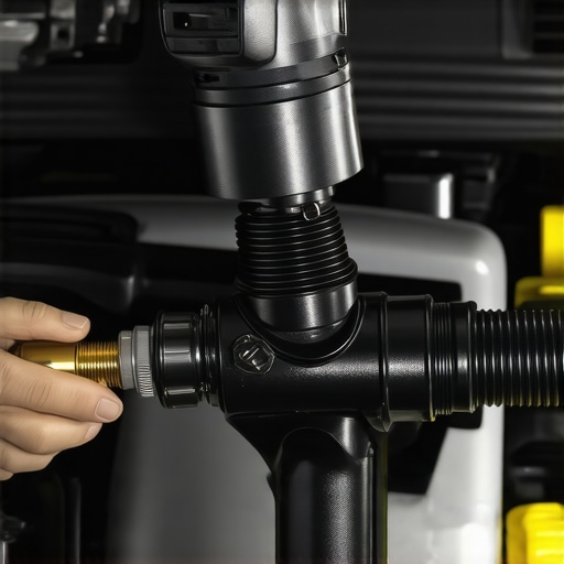
Composite intake manifolds save weight and lower manufacturing costs, but they introduce a frustrating diagnostic variable: thermal expansion mismatch. Plastic composites and cast aluminum cylinder heads expand at wildly different rates as they heat up. A cold engine might run flawlessly, only to develop a rough idle and lean codes once the engine bay reaches normal operating temperatures. To catch these elusive leaks, you must monitor live engine data while applying localized heat or cooling directly to the manifold seams. If your short-term fuel trim suddenly spikes when thermal expansion occurs, you have successfully narrowed down the physical distortion point.
Why do composite intake manifolds crack more frequently than cast iron?
Unlike traditional cast iron or heavy aluminum units, modern composite manifolds are constructed from reinforced thermoplastics. While highly durable, they are susceptible to heat cycles, engine vibrations, and the physical stress of overtightened mounting bolts. Over time, these forces cause microscopic stress fractures near the cylinder head mating surfaces. Because these plastics cannot warp or flex back like metal, the crack remains open once a thermal threshold is crossed, creating a persistent path for unmetered air to enter the combustion chambers.
The Evaporative Emissions Connection and Purge Valve Failures
An overlooked source of unmetered air is the Evaporative Emissions (EVAP) system. Specifically, a purge valve that is stuck partially open allows raw fuel vapors and raw atmospheric air to pull directly from the charcoal canister into the intake manifold. This creates a highly erratic air-fuel ratio that mimics a traditional vacuum leak but behaves differently under physical load. Because the purge valve is electronically controlled, checking its mechanical sealing integrity requires physically isolating the valve from the intake manifold and applying a hand-held vacuum pump to verify it holds pressure when de-energized.
According to the technical standards maintained by the International Organization for Standardization (ISO), automotive vapor recovery systems must remain hermetically sealed under varying engine loads to prevent hydrocarbon emissions from escaping into the atmosphere. When a purge solenoid fails to seal, it violates these emission standards and disrupts the stoichiometric calculations of the engine control unit. If you suspect an EVAP failure is behind your vehicle’s poor performance, adjusting your diagnostic approach to isolate this subsystem is the next critical step. Explore our detailed guide on mechanic tips for diagnosing common auto problems to master these tricky isolation procedures.
Mapping the Intake Manifold Runner Control System
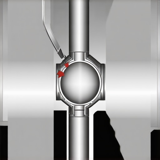
Many modern variable-geometry intake systems utilize Intake Manifold Runner Control (IMRC) valves to optimize airflow velocity at different engine speeds. These systems use vacuum-actuated diaphragms or small electric motors to rotate butterflies inside the intake runners. The shafts of these runner butterfly valves penetrate the composite manifold body and are sealed with small rubber O-rings. Over hundreds of thousands of engine rotations, these shaft seals wear down, creating a tiny, hidden leak path directly into the individual intake runners that is virtually impossible to see from the outside.
These rotational shaft seals are subject to constant friction and high thermal loads, making them prime candidates for progressive degradation. When the O-rings harden, they allow unmetered air to slip past the butterfly shafts directly into the cylinder runners, often causing cylinder-specific misfires that baffle standard diagnostic routines. Because this air entry occurs downstream of the main plenum, traditional smoke testing at the throttle body may not build enough localized pressure to force smoke out through these tightly recessed seals. To pinpoint a worn runner shaft seal, a technician must monitor individual cylinder fuel trims or misfire counters while carefully directing a highly localized stream of vapor or chemical tracer directly at the pivot points of the IMRC actuator linkage.
Why do variable geometry intake runner seals fail only at high engine loads?
Variable geometry intake runner seals often experience dynamic failure because the position of the IMRC shaft changes based on engine load and RPM. At idle, the butterfly valves are closed to increase air velocity, holding the shaft in a specific physical position where the worn seal might still maintain a marginal seat. However, once the engine control unit commands the actuator to rotate the shaft open at higher RPMs, the physical shifting of the worn shaft against the hardened rubber O-ring exposes the flat spots and micro-tears. This dynamic shifting creates a transient vacuum leak that only manifests during transition phases, making it exceptionally difficult to detect with static workshop tests.
Diagnosing these transient sealing failures requires a highly structured approach that combines mechanical isolation with real-time data capture. According to diagnostic standards established by the Equipment and Tool Institute (ETI), capturing high-frequency sensor data during simulated road tests is the most reliable method for identifying erratic air-fuel ratio deviations caused by moving actuator components. When the vacuum leak only occurs during physical valve transition, recording the PID data for both the IMRC position sensor and the short-term fuel trim allows you to overlay the graphs and confirm if the fuel spike correlates perfectly with the physical movement of the shaft. For vehicle owners dealing with these complex, load-sensitive performance drops, seeking a specialized skilled mechanic you can trust is the most efficient path to preventing unnecessary parts replacement. Have you encountered an elusive engine hesitation that only occurs during acceleration? Share your diagnostic journey in the comments below or read our detailed guide on resolving hidden engine issues.
Expert Insights & Advanced Considerations
Runner Shaft Sealing Failure Under Varying Loads
Diagnostic technicians often run into dead ends trying to find a vacuum leak when checking a static engine in a service bay. Because the Intake Manifold Runner Control (IMRC) shaft rotates based on RPM and load, a seal may only open up and fail when the vehicle is physically driven. If you are tracking down an elusive lean code that only shows up on highway merges, focus on dynamic testing using live data stream captures during actual drive cycles rather than relying on stationary garage tests.
The Risk of Thermal Expansion Over-Tightening
Many vehicle owners assume a leaking composite manifold gasket simply needs to be tightened down further to fix the issue. In reality, over-torqueing mounting bolts on composite plastic parts will distort the mating surface permanently, leading to severe thermal-creep leaks. Always utilize a calibrated inch-pound torque wrench and strictly follow the manufacturer’s specified tightening sequence to avoid causing an expensive auto repair bill.
Why Liquid Solvents Do Not Reveal Runner Shaft Pinholes
Using brake cleaner or starting fluid to detect air leaks around recessed butterfly valves is highly ineffective. The liquid solvent cannot easily penetrate the tight, recessed clearances of the runner shaft linkages where the physical O-rings reside. Utilizing a visual smoke medium or specialized tracing vapors is the only reliable way to pinpoint degradation inside these intricate, recessed assemblies.
Curated Expert Resources
Society of Automotive Engineers (SAE) Technical Papers
This resource offers peer-reviewed research and highly detailed engineering analyses on automotive sealing technology, polymer degradation under high engine temperatures, and modern intake manifold air velocity dynamics.
Bosch Mobility Solutions System Technical Manuals
Provides exceptional schematic breakdowns and precise technical descriptions of variable-geometry intake manifolds, vacuum-actuated control solenoids, and electronic throttle body integration standards.
Equipment and Tool Institute (ETI) Diagnostic Frameworks
An outstanding source for understanding advanced OBD-II data logging techniques, highlighting how to properly map fuel trim spikes against active engine load variables to identify transient vacuum leaks.
Final Expert Perspective
Accurately identifying dynamic and thermal air leaks in modern variable-geometry engines requires moving beyond old-school diagnostic habits and embracing targeted testing strategies. Simply replacing components without analyzing live fuel trims under load often leads to wasted time and unnecessary expenses. If you suspect your vehicle is suffering from unmetered air intrusion, we encourage you to study our guide on mechanic tips for diagnosing common auto problems or review the proper procedures to choose a skilled mechanic you can trust to help resolve these complex driveability dilemmas.